Stanford FS752 GNSS Time and Frequency Reference

Stanford FS752 GNSS Time and Frequency Reference
GPS 10MHz frequency reference

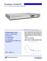
The FS752 GNSS Disciplined Time and Frequency Reference provides calibrated time and frequency distribution to your laboratory. A built-in receiver tracks any of the four major GNSS constellations: GPS, GLONASS, BEIDOU, or GALILEO. The instrument comes with a double-oven OCXO timebase that has phase noise of less than -125dBc/Hz at 10Hz offset.
Features:
- GPS/GNSS disciplined 10 MHz
- Double-oven OCXO timebase
- Low phase noise
- Five 10 MHz outputs
- Two 1pps outputs
- Up to either additional 10 MHz & 1 pps outputs (opt.)
10 MHz and 1 pps Distribution
The FS752 provides five buffered 10 MHz outputs and two buffered 1 pps outputs. The 10MHz outputs generate 1Vrms into 50 Ω and may be used as frequency references for laboratory equipment. The 1 pps outputs generate 10 μs pulses, with 5 V CMOS logic and rising edges aligned to UTC. Up to eight additional 10 MHz and 1 pps outputs are available as rear-panel options.
GNSS Receiver
The FS752 provides bias for a remote active GNSS antenna. The unit's GNSS receiver tracks all satellites in view, automatically surveys and fixes its position, then uses all received signals to optimise its timing solution. The FS752 time-tags the 1pps output from the receiver, corrects the result for the receiver's sawtooth error, then phase locks the timebase to the GNSS 1 pps. The TDEV between two instruments is a few nanoseconds.
If the GNSS signal is lost, the timebase is left at the last locked frequency value. The timebase will age or drift in frequency by less than ±0.05 ppm/year.
GNSS Antennas
You may choose to purchase a GNSS antenna from SRS, or a third party, or use an existing GNSS antenna at your facility. SRS timing receivers require a net gain (after cable losses) of +20 dBi to +32 dBi, which is a very common level from a variety of available active antennas and typical cable lengths. The antenna input to SRS timing receivers have a female BNC connector, provide +5 V bias, and have a 50 Ω input impedance.
SRS offers two antenna solutions, both of which have LNAs. All systems components have a 50 Ω characteristic impedance.
Alarms
The FS752 includes a configurable SPDT switch on its rear panel. By default, the alarm is set to assert whenever the FS752 loses lock to the GNSS signal, but the switch can also be set to monitor the health of the timebase or the instrument's holdover state.
Communication
The FS752 can be controlled and queried over its USB port. The instrument is fully programmable using its extensive high-level command set, and there is also a free GNSSDO application that makes sending commands, viewing instrument status, and changing the configuration of the FS752 easy.
For further information please contact us or download the datasheet.

